
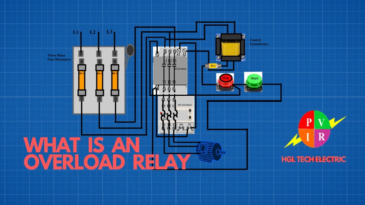
What Is an Overload Relay? The Definitive Guide
5 AF CONTACTORS AND OVERLOAD RELAYS GUIDE 6 Installation and commissioning for contactors 63 6.1 Mounting 63 6.2 Changing main contacts, arc chutes, and coils 66 6.3 Connection 67 7 General product overview Overlad relays 72 7.1 Basic function 72 7.2 Principle of operation 74 7.3 Terms and ratings 76
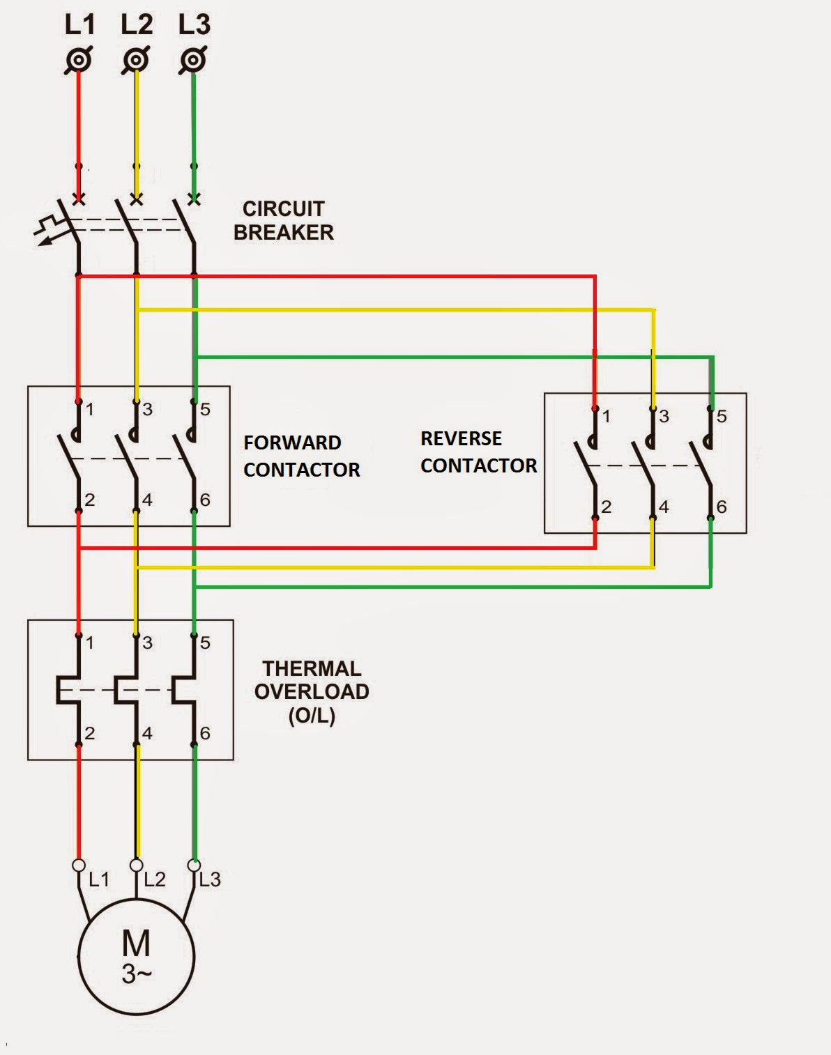
Wiring Diagram Thermal Overload Relay
Thermal overload relays Solid state overload relays 3RU21 overload relays up to 100 A with screw connection, CLASS 10 Page Selection and ordering data. Circuit diagrams 3/15 Dimension drawings 3/16 - 3/17 Description 3/52 - 3/53 Technical data 3/58 - 3/62 SIRIUS 3RV motor starter protectors up to 100 A
Overload relay and contactor wiring connection YouTube
The overload relays have a setting scale in Amperes, which allows the direct adjusting of the relay without any additional calculation. In compliance with. Technical diagrams 140 120 0 20 40 60 80 100 02 04 06 08 01 00 (%) t = 1 s a t = 1.5 s a t = 3 s a t = 5 a s t = 0.5 s a duty ratio switching fr equency (Op/h) 40 20 10 6 4 3 2 1 11 34 56.

How to work overload relay। overload relay connection। overload relay working principle. YouTube
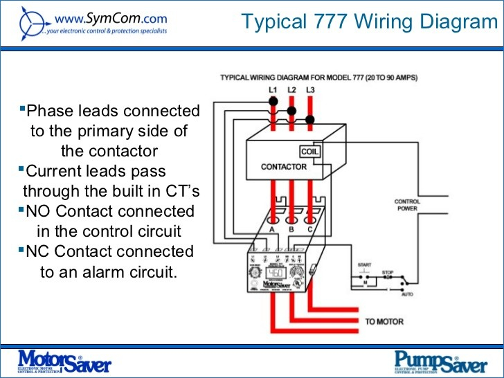
E1 Plus PROFIBUSTM module. The 193-EPRB PROFIBUS network communication module delivers direct access to motor performance and diagnostic data on a field bus-based network and seamless control. The PROFIBUS communication module supports both PROFIBUS DP- V0 and DP-V1. Protective functions include overload warning, jam protection, and underload.

⭐ Thermal Overload Relay Wiring Diagram ⭐ Aerden dnd
Overload Relay Wiring Diagram Whenever the flow of current toward the motor is more than what the heaters are charged for, the overload explores later than some seconds. The classes of overload relay can be classified into three types based on the duration of relay explore.
Electrical Standards Overload relay working principle and features of thermal motor overload
SIRIUS Innovations - Thermal Overload Relays SIRIUS 3RU2 / Solid-State Overload Relays SIRIUS 3RB3 Edition Answers for industry. 09/2014.. Circuit diagrams 12 Types of coordination A References B Dimension drawings (dimensions in mm) C Correction sheet D . Siemens AG Industry Sector Postfach 48 48
Wiring Diagram Thermal Overload Relay Diagram
The electronics accurately identify excessive current or phase loss and react to the condition with greater speed, reliability and repeatability than a traditional electromechanical device. How do you know your overload is working? Single blink: Normal operation Double blink: Fault condition developing
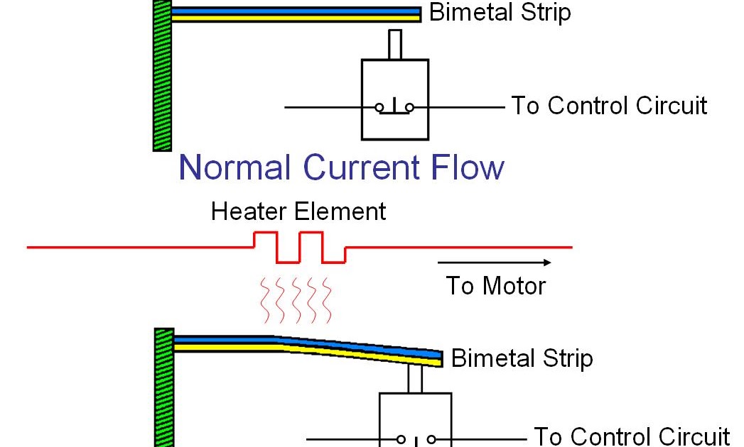
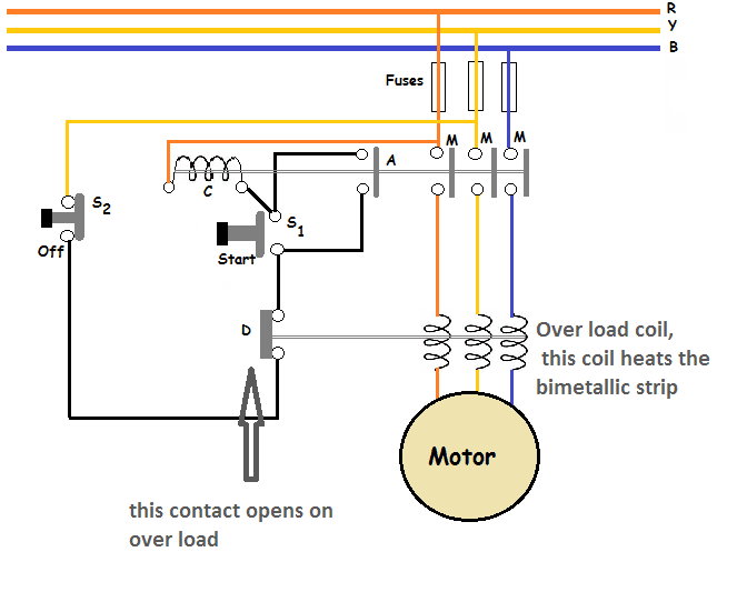
Motor Starters The bimetallic Overload Relay
Thermal overload relays Solid state overload relays 3RU21 overload relays up to 100 A with screw connection, CLASS 10 Page Selection and ordering data • Basic Unit 3/10. Circuit diagrams 3/15 Dimension drawings 3/16 - 3/17 Description 3/52 - 3/53 Technical data 3/58 - 3/62 SIRIUS 3RV motor starter protectors up to 100 A.
Pengertian Thermal Overload Relay (TOR) Lengkap hingga paham.
Overload relays are devices that protect electric motors from overloads and phase failure. When the motor is overloaded, it detects this and terminates the power flow, preventing the motor from overheating and winding damage. It can also protect the motor from phase loss/failures and phase imbalance, in addition to overloads.

Overload Relay Principle of operation YouTube
An overload trip occurs when the value reaches 100%. Adjustable Settings Configure thermal overload protection by programming the motor's full load current (FLC) rating and the desired trip class (5…30). Programming the actual values via software ensures the accuracy of the protection.
Siemens Overload Relay Wiring Diagram Cocraft
overload relay has no power contacts and cannot disconnect the motor by itself. The control circuit contact must be wired in series with the coil of the contactor so that the contactor will de-energize when an overload occurs. Square D manufactures three types of overload relays, the melting alloy, the bimetallic, and solid state.
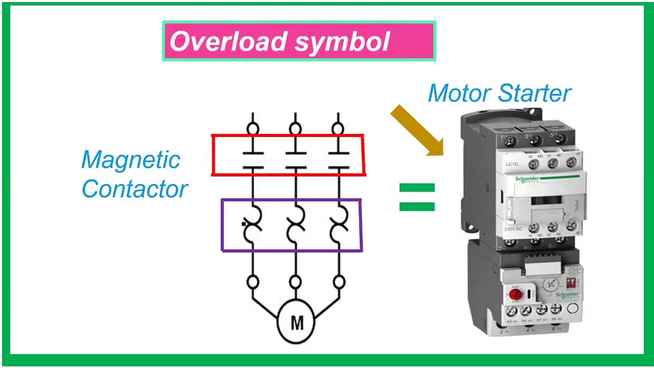
overload relay schematic
aM in conjunction with the thermal overload relay. The specifications in relation to short-circuit protection for contactors and overload relays must be noted when selecting the rating of fuses or circuit-breakers. Efficiency of protection device: not effective partly effective fully effective SST 081 91 M 2 SST 081 91 M 1 SST 081 91 M 3
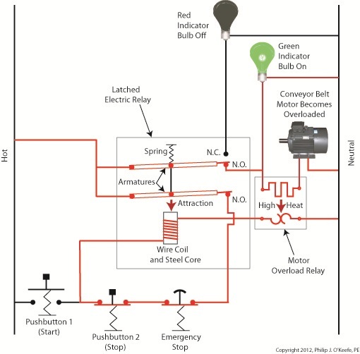
Industrial Control Basics Motor Overload Relay In Action Engineering Expert Witness Blog
The examples and diagrams in this manual are included solely for illustrative purposes. Because of the many variables and. E300 Electronic Overload Relay Installation Instructions, publication 193-IN080 Provides complete user information for the E300 Electronic Overload Relay.
Electrical Standards Overload relay working principle and features of thermal motor overload
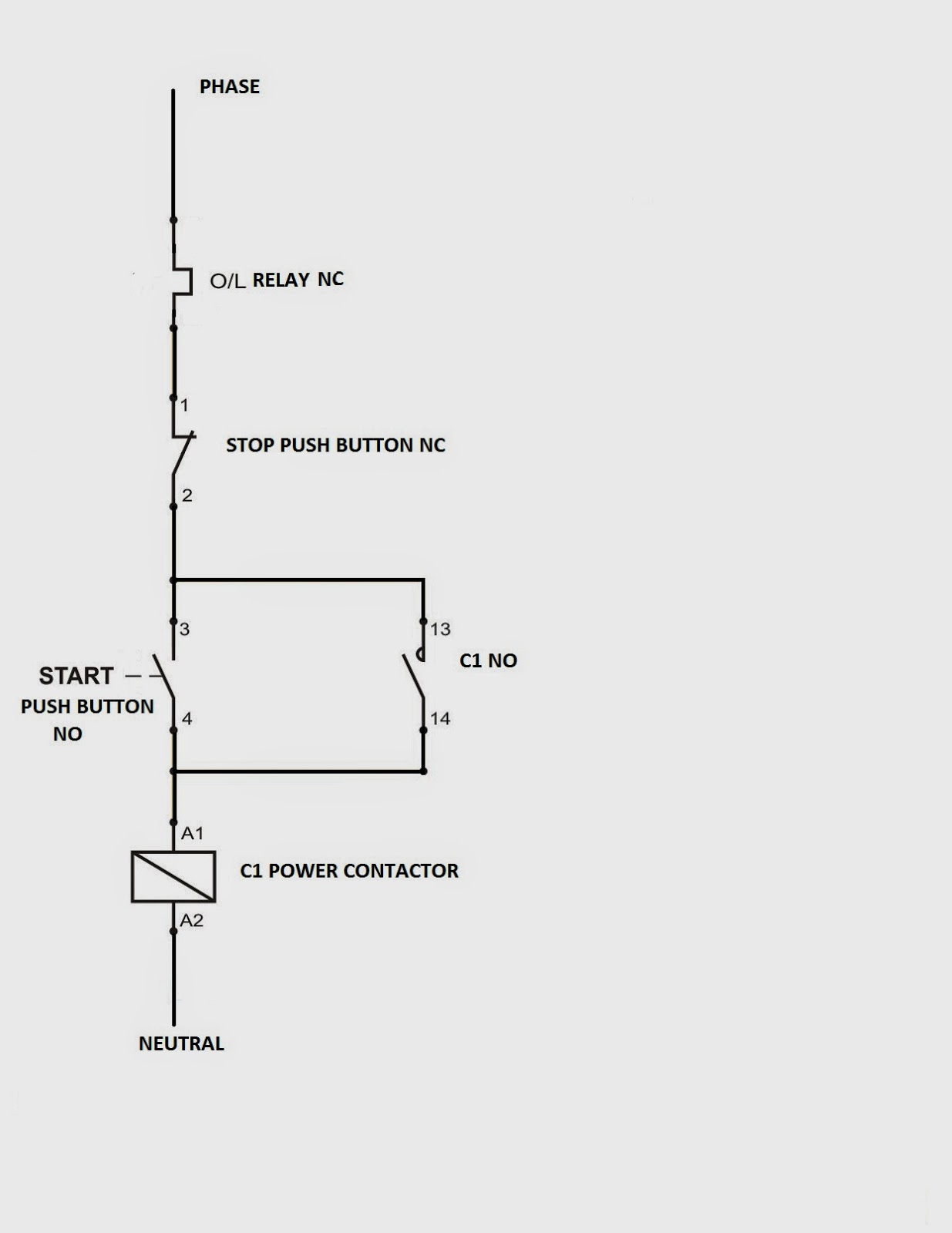
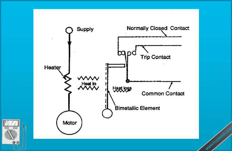
Connection Diagram of Overload Relay: Overload Relay Working Principle: Parts of Overload Relay: #1. Terminal: #2. Ampere Range Setting: #3. Reset Button: #4. Auxiliary Contact: #5. Test Button: Overload Relay Types: #1. Thermal Overload Relay: #2. Magnetic Overload Relay: #3. Bimetallic Thermal Overload Relay: #4. Electronic Overload Relay: #5.
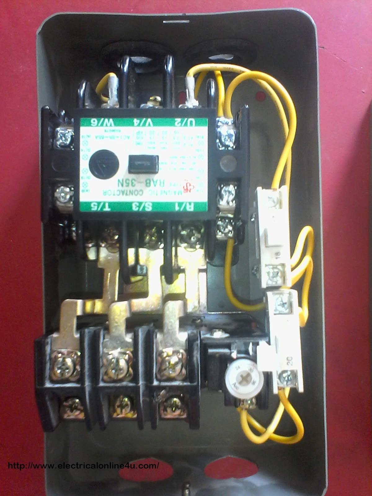
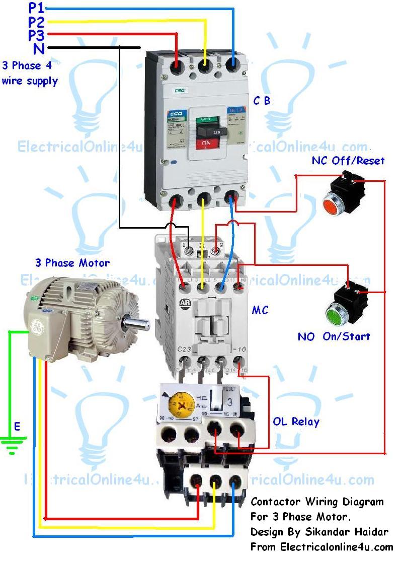
How To Wire Contactor And Overload Relay Contactor Wiring Diagram Electrical Online 4u All
The E100 Electronic Overload Relay is the next generation basic-tier electronic overload relay. It has enhanced features to better safeguard your motor protection investments, including increased accuracy and repeatability, a self-powered design with lower heat dissipation, and the certifications to comply with many applications.

Electrical Standards Overload relay working principle and features of thermal motor overload
Step-by-Step Instructions for Connecting a Thermal Overload Relay. Step 1: Start by identifying the terminals on the thermal overload relay. Typically, there are three terminals: L1, L2, and L3. L1 and L3 are the line terminals, while L2 is the load terminal. Step 2: Ensure that the power supply to the motor is turned off.